

System Requirements
The system requirements for VERSAware Plus on a Windows PC can vary depending on the specific software application and its version. Here are some general guidelines for the typical system requirements:
Minimum system requirements:
- Operating System: Windows 7 or later (32-bit / 64-bit version)
- Processor: Intel Core i3 or equivalent AMD processor
- RAM: 4 GB or higher
- Hard Disk Space: 20 GB or more (depending on the software and additional data storage requirements)
- USB Ports: sufficient available USB ports for connecting the robotic workstation and other peripherals.
Recommended system requirements:
- Operating System: Windows 11 (64-bit version)
- Processor: Intel Core i5 or equivalent AMD processor
- RAM: 12 GB or higher
- Hard Disk Space: 50 GB or more (depending on the software and additional data storage requirements)
- USB Ports: multiple available USB ports for connecting the robotic workstation, barcode scanners and other peripherals.
It is essential to keep in mind that these are general guidelines and the actual system requirements can vary based on the complexity of the automation tasks, the size of the data being processed and any additional software modules or accessories being used.
Before installing the liquid handling robotic workstation automation software, it is recommended to check the software documentation or contact the software vendor for the specific system requirements for their application to ensure that your Windows PC meets the necessary specifications for optimal performance and compatibility.
Windows Configuration
The VERSAware Plus software installation can be conducted only after ensuring that the current Windows user account is the administrator account, User Account Control is disabled in both Control Panel and Windows Registry, .NET Framework 4.5.2 components and CDM212364 USB driver are successfully installed.

Please ensure that a Windows user account with administrative permissions is used during the VERSAware Plus software installation and operation as displayed in “Control Panel → User Accounts”.

Set User Account Control to “Never notify” in “Control Panel → User Accounts → Change User Account Control settings” before software installation on all Windows platforms. Restart the computer at this stage if updating EnableLUA in Windows Registry isn’t required on Windows 7 and 8.

On Windows 10 and 11 only, set EnableLUA to zero in “File Explorer → C:\Windows\regedit.exe → HKEY_LOCAL_MACHINE\SOFTWARE\Microsoft\Windows\CurrentVersion\Policies\System” before software installation and restart the computer.
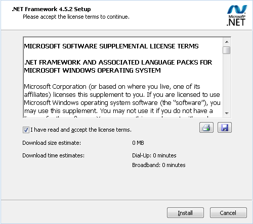
On Windows 7 and 8 only, locate and run “NDP452-KB2901907-x86-x64-AllOS-ENU.exe”, acknowledge the license terms and click “Install” to continue.

.NET Framework 4.5.2 installation progress as required for Windows 7 and 8.

.NET Framework 4.5.2 installation is completed as required by Windows 7 and 8.
Windows Power Options will need to be disabled in “Control Panel → Power Options” to ensure continuous instrument operation without interruptions.

Please set “Put the computer to sleep” to Never in “Control Panel → Power Options → Change plan settings”.

Set “Turn off hard disk after” to Never, “Sleep after” to Never, “Allow hybrid sleep” to Off, “Hibernate after” to Never, “USB selective suspend setting” to Disabled in “Control Panel → Power Options → Change plan settings → Change advanced power settings”.
Software Installation
Save the VERSAware Plus installer file to a location on your computer. Navigate to the folder where you saved the installer file. Double-click on the installer file to run it, it should start the installation process.

Windows might display a User Account Control prompt asking for permission to make changes to your system. Click “Yes” to proceed. The installer will display a welcome screen and an introductory message. Read through it and click “Next”.

The installer will allow you to choose the installation location (folder) for the software. You can usually stick with the default location or choose a different one. Click “Next”.
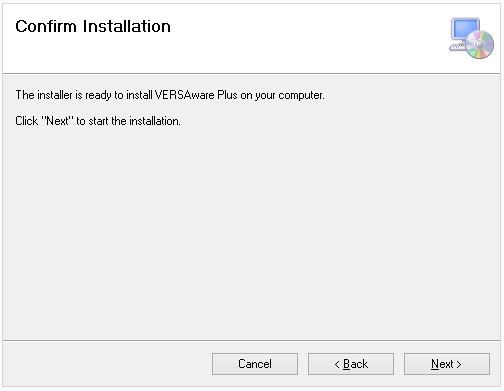
Click the “Next” button to initiate the installation process.

The installer will display the progress of the installation. This might involve copying files, configuring settings and more.

Once the installation is finished, you’ll see a completion screen. This will inform you that the installation was successful. Click “Close”.
Driver Installation
Locate the drivers specifically designed for your USB device model and the version of Windows you are using. Navigate to the folder where the drivers are located, select the appropriate driver file and press “Enter”.

Follow the on-screen instructions to extract the files.

The installation process starts with a setup wizard. Click “Next” to proceed.

Carefully read the software’s license agreement. If you agree, select the checkbox indicating acceptance, then click “Next”.

Once the installation is complete, you’ll see a “Finish” button. Click it to close the installer.
Locate the “AccessDatabaseEngine.exe” utility that is required for all MS Excel import / export operations in the VERSAware Plus software and launch the file execution.

Select “Next” to continue with the installation process.
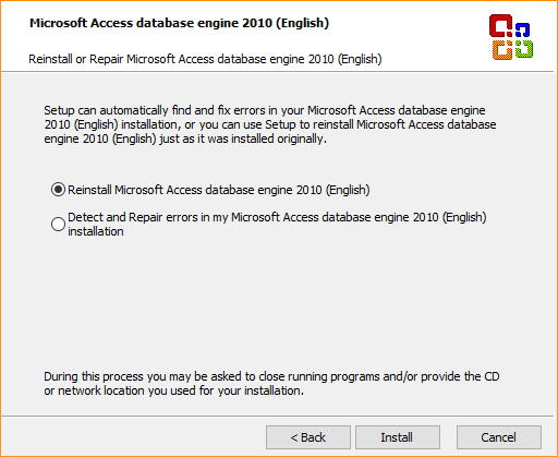
Choose to install or re-install the Microsoft Access database engine. Click “Install” to continue.

The installation progress is shown here. Patiently wait for its completion.

The Microsoft Access database engine installation is complete. Click “OK”.
Starting Software
Navigate to the location where the software is installed, usually in the “Program Files” or “Program Files (x86)” directory. Find the executable file (with an “.exe” extension) and double-click it to launch the software.

Software Login
The primary purpose of the software login is to authenticate users by requiring them to provide valid credentials before granting them access to the software’s features, functionalities or content:
- Username Field: this is where users input their unique username. It’s the initial piece of information the software uses to identify the user.
- Password Field: the password field is used for users to enter their secret password associated with their account. Passwords are typically masked (displayed as dots or asterisks) for security purposes.
A blank default password should be used for the Administrator account to log in.

Main Interface
The main interface is designed to provide users with a user-friendly and intuitive platform to control and manage the robotic system’s operations related to liquid handling tasks. This interface serves as the central hub through which users can interact with the robotic system, set up experiments, define protocols and monitor progress. Here’s a breakdown of the main components:
- File Menu Options: a menu for calibrating the robotic system’s various components, such as robotic arms, pipetting heads, shakers and temperature control devices. This ensures accurate and consistent performance.
- Toolbar Functions: the software comes equipped with a variety of toolbar functions that facilitate the operation and control of liquid handling robots. These functions are designed to streamline the setup, execution and monitoring of liquid handling tasks, making the process more efficient and user-friendly.
- Deck Layout: a visual representation of the robotic system’s deck, where users can define the arrangement of labware, such as plates, tubes, reservoirs, adapters, reagent cooler blocks and tip boxes. This layout helps plan the execution of protocols by specifying where different reagents and samples are located.
- Action Manager: an action manager refers to a crucial component that facilitates the creation, scheduling, execution and monitoring of various liquid handling tasks performed by the robotic workstation. This software component acts as a control center that allows users to design, automate and manage a wide range of liquid handling processes with precision and efficiency.
- Sequence Manager: this section enables users to schedule, organize and execute multiple protocols in a sequential manner. Users can select protocols, assign labware and define the order of operations.
- Protocol Editor: a feature that allows users to create, modify and save protocols for liquid handling tasks. Users can define specific actions like pipetting, mixing and dispensing, as well as define parameters such as volumes, timings and source / destination locations.
- Labware Management: the software provides options to define and manage different types of labware, such as microplates, tubes and tip racks. Users can specify well formats, capacities and other characteristics.
- Progress Monitor: this screen provides an overview of ongoing processes and access to various functionalities.

Deck Layout
Right-click an empty deck position to display the plate library selection interface. Double-click an occupied position to remove its plate or adapter. Hover the mouse over the center of a plate to display the plate code that can be used to locate the required labware to update the offsets.

Plate Library
The plate library selection interface consists of the following plate types:
- Regular Plates: 96-well plates, 96-deep well plates, 384-well plates, PCR plates, SPE plates
- Rack Holders: tube holders, cartridge racks, collectors
- Reservoirs: standard reservoirs, irregular reservoirs (with variable column sizes)
- Reagent Coolers: asymmetric reagent cooler blocks (for tubes with different volumes)
- Tip Boxes: single-channel tip boxes, multi-channel tip boxes, dual tip boxes
- Adapters: PCR plate adapters, magnet adapters, shaker adapters
- Advanced: pressure module, nitrogen dryer, 96-channel aspirator
Click on plates to select at least a single source and a single destination plate for liquid handling actions. Adapters are special devices that can be placed under the plates such as unskirted PCR plates and PCR strips. Liquid handling actions allow users to select both plates and adapters.

Right-click an occupied plate position either on the deck or in the plate library to display an optional plate or adapter image along with the catalog number if available.

Tip Boxes
At a minimum, a single tip box is required for liquid handling operations. Tip boxes include three types:
- Single-Channel Tip Boxes: tip barrel #8 is typically used to engage a single tip
- Multi-Channel Tip Boxes: 8-channel tip boxes, 4-channel tip boxes
- Dual Tip Box: a special tip box with programmable different tip types (20 µL, 50 µL, 200 µL, 1000 µL) in various columns (a dual tip box can either be assigned single-channel or multi-channel tips)

Right-click a tip box on the deck to display the read-only interface to monitor and manually reload the tip box columns with adequate tips.

Toolbar
Most frequently used functions are assigned to the toolbar buttons. Some of the commonly used buttons include:
- Add a New Folder: creates a folder for the new protocol
- Add a New Assay: adds an assay to the new protocol (a folder needs to be selected)
- Add a Sequence: adds a sequence to an assay with multiple actions (an assay or a sequence needs to be selected)
- Delete an Assay: permanently deletes a folder, an assay or a sequence (no backup is available unless there is a backup of the entire database)
- Import a Sequence: imports a sequence from an XML file
- Export a Sequence: exports a sequence to an XML file
- Transfer Tips: executes a robotic arm movement sequence to transfer 8-chanel tips into a single-channel tip box

If the tip transfer is required, select a source tip box, a target tip box location along with matching tip box columns. A prior instrument initialization is required with the “Home” button. Click “Transfer Tips” to execute the sequence.

Creating Folder, Assay, Sequence
Click “Add a New Folder” to add a folder for the new protocol. The display view order can also be assigned.

Click “Add a New Assay” to add an assay to the new protocol. As an option, assays can be copied from the list of existing assays. The display view order can also be assigned.

Click “Add a Sequence” to add a sequence to an assay. As an option, sequences can be copied from the list of existing sequences. A sequence can be added with or without actions. The display view order can also be assigned.

Selecting Protocols
Navigate to the desired pre-programmed protocol and load a sequence.

Programming Protocols
The drag and drop functionality allows users to create protocols by manipulating various action elements. At least a single valid action is required to save the protocol. Liquid Transfer is the main liquid handling action used in protocols for reagent addition, plate replication, plate reformatting and liquid sample transfer. Click “Clear” to erase existing table action records and select “Edit” to modify action parameters. Furthermore, the drag and drop interface is supported when changing the action execution order is required within a sequence. Actions can be deleted and duplicated, as well.

Liquid Transfer
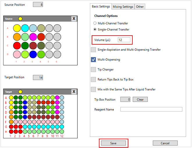
The Liquid Transfer action is the main function used for all liquid handling operations. Select source and target plates using the deck plate position selection interface, click “Multi-Dispensing”, choose either single-channel or multi-channel mode, enter the desired volume in µL. Plate well selection is conducted according to the selected color as displayed in the circle above the plates. Click on the circle to assign the appropriate plate well color. Selected source and target plate well colors should match for the software to be able to validate, save and execute correct liquid transfers. Additional tip changer and tip box options are available on the same screen, as well. A tip box used for the selected liquid transfer is either selected in settings or automatically assigned by the software. Then click “Save” to finish action editing and close the window.
Mixing options for reagents and liquid samples are available on the next tab. These options include mixing with disposable pipetting tips or using a shaker device module for the plate on that module. Volumes in µL, mixing depth in mm will need to be set or alternatively the shaking speed in RPM and the shaking duration. Optional one-directional / bi-directional shaking mode as well as the background mode can be selected. The background shaking mode is typically used during the simultaneous liquid handling operation. Standard mixing options apply to many other various liquid handling actions throughout the software, as well as the stand-alone Mixing with Tips action.

Running Sequence
After having finished with action editing, save the sequence and try to initialize the liquid handling workstation using the respective navigation toolbar buttons:
- Home Button: this button allows the robotic arm to return to its home or initial position, ensuring that the arm starts from a known location before executing any tasks.
- Run Button: before pressing this button, users generally need to select the specific protocol or pipetting task they want to execute. This involves choosing from a list of saved protocols or creating a new one.
- Save Button: the primary purpose of this button is to save the current state of your configured protocol or settings. This includes parameters like pipetting volumes, source and destination wells, tip usage, mixing steps and other details.
Sequence execution is conducted strictly in a sequential manner with options to pause, resume, stop and repeat the experiment. In case of hardware connection errors or incorrect communication settings, please refer to the next section of this chapter.

Troubleshooting Communication
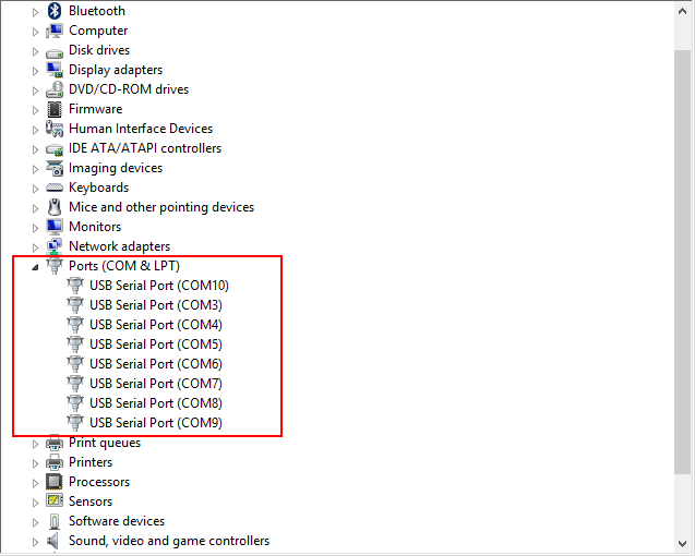
Checking COM ports in the Device Manager when running a robotic workstation is a common troubleshooting step to ensure proper communication between the workstation and the computer. COM ports are used to establish serial communication connections between devices, and they play a crucial role in controlling and monitoring robotic instruments. Here’s how you can check COM ports in the Device Manager:
- Open Device Manager: right-click on the Start button and select “Device Manager”.
- Expand Ports (COM & LPT): in the Device Manager window, locate and expand the section labeled “Ports (COM & LPT).” This section displays all available COM ports on your computer.
- Identify Robotic Instrument Port: look for the COM port associated with your robotic liquid handling workstation.
- Verify Connection Status: check if the COM port associated with your robotic workstation is listed and if it has a status indicating that it’s working properly. If there are any issues, the port might display a warning symbol or an error message.
- Monitor COM Port Activity: you can also monitor the activity of the COM port while the robotic workstation is running. If the workstation is actively communicating with the computer, you might see intermittent data flow indicators.
- Update or Troubleshoot: if the COM port is not functioning as expected, you might need to troubleshoot the issue. This could involve checking cable connections and reinstalling drivers.
- Port Number and Settings: note down the COM port number associated with your robotic workstation. You might need this information when configuring the communication settings in the workstation’s software.
COM Ports and Motorboards
Adjusting COM port settings in the workstation’s software involves configuring the communication parameters to establish a reliable connection between the software and the robotic instrument. Here’s a guide on how to adjust COM port settings:
- Open Software and Navigate: launch the VERSAware Plus software on your computer. Navigate to the settings or configuration section for various devices where you can adjust the communication settings in “Tools → Electronic Boards, Devices and COM Ports”.
- Select COM Ports: in the communication settings, you’ll find options to select or specify the COM ports that your robotic instrument and devices are connected to. This is where you’ll configure the software to communicate with the correct port.
- Update Table: then click “Update Motor Board” and restart the software if necessary.

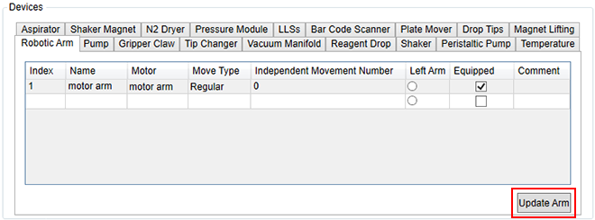
After having finished with the COM port adjustment, corresponding motorboards and devices will need to be correctly selected and assigned to various equipped modules. Then click “Update Arm” to save the table and close the window.
Labware Settings
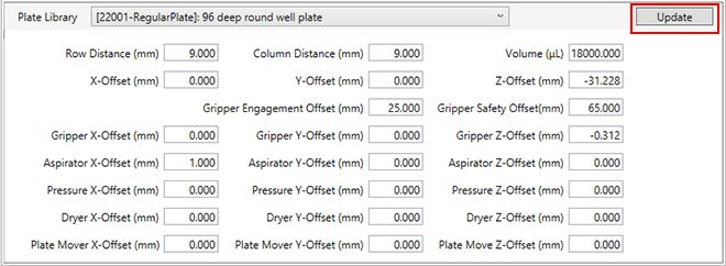
Labware settings do not require updating sequences. In the plate library section, locate the required plate code for standard plates. Physical plate measurements, column / row distance and offsets in mm are located on this screen. Each standard plate can be adjusted for precise positioning along three X,Y,Z-axes for the following devices:
- Robotic Arm: a reference to the standard 96-well round bottom plate used for teaching plate deck positions
- Gripper Arm: a reference to the taught gripper position in “Tools → Device Calibration → gripper door”
- 96-channel Aspirator: a reference to the engaged 96-channel aspirator module
- Gripper Arm: when plate is engaged, a reference to the engagement position
- Pressure Module: a reference to the engaged pressure module
- Nitrogen Dryer: a reference to the engaged nitrogen dryer module
- Plate Mover: when plate is engaged for the VERSA 10 instrument only, a reference to the engagement position
All X,Y-gripper offsets as well as pressure module, nitrogen dryer and plate mover always refer to the robotic arm in contrast to the Z-gripper offset which refers to the gripper arm in all setting configuration sections. Each standard plate is defined by the number of rows and columns, as well. These settings can be found in “Tools → Plate Library”. Click “Update” to save the settings. There is no need to update the protocols for the settings to take effect.
Tip boxes will have the following parameters along with measured column / row distance in mm:
- Tip Length (mm): total tip length that affects arm positioning within the plate
- Max Volume (µL): maximum adjusted tip volume depending on the tip filter
- Air Gap Volume (µL): default tip air gap setting, can also be adjusted in “Sequence Settings → Tip Air Gap Settings”
- X,Y,Z-Offset (mm): a reference of the tip barrels on the top surface of the tip box without tip engagement to the teaching plate type
- Return Tips / Z-Offset (mm): a Z-height for returning the tips back to the original tip box
- Engagement Depth (mm): tip barrel engagement depth inside the tips that affects arm positioning
- Dispose of Tips / Z-Offset (mm): a Z-height above the tip chute during the tip ejection sequence
- Waste Liquid Disposal / Z-Offset (mm): a Z-height above the waste station during the waste disposal
Tip engagement speed settings for the robotic Z-arm:
- Start Speed (step/s): reduced initial speed during the tip engagement
- End Speed (step/s): reduced final speed during the tip engagement
- Acceleration (step/s2): reduced rate of speed change during the tip engagement
In addition, tip boxes can be configured as single-channel / multi-channel or as a dual tip box. However at the present, there is only a single dual tip box configuration available in the software. Then click “Update” to save the settings.

Asymmetric or irregular plates are comprised of symmetric partitions. Each partition is configured in the similar way to standard plates. Unlike the “Tools → Plate Library” settings for the total number of rows and columns, each partition will have its own columns / rows setting in the table that is displayed here. “Left” and “Top” settings in pixels refer to the plate partition icon display on the deck. X,Y-Z-offsets are displayed for editing according to the table row selection. These offsets represent the reference to the taught plate deck position with the standard 96-well plate unless the reagent cooler block is firmly mounted on the deck. Then click “Update” to save all modified settings.

Plate adapters are used as a stand on the deck for unskirted PCR plates and PCR strip tubes. Shaker adapters and magnet adapters are used for the 96-deep well plates. Other 96-well or 384-well plates might be used with portable cooler adapters, as well. Adapters have similar configuration settings as compared with standard plates with the exception of the additional arm adapter plate offset and gripper adapter plate offset tables. Gripper X,Y,Z-offsets are not used for the engaged adapter itself with the gripper arm but rather for the engaged plate on top of the adapter. Adapters also don’t have settings for the pressure module, nitrogen dryer and the plate mover offsets.

Two additional tables with offset setting adjustments are available for the adapters to apply to plates as long as the plates are placed on top of the adapters:
- Configure Arm Offsets: additional arm positioning offset adjustment for each individual adapter plate
- Configure Gripper Offsets: additional gripper adapter plate offset adjustment for each engaged individual plate
“DR Compensation” stands for “Detection Range Compensation” which is used to adjust the liquid level sensing (LLS) signal in the range of 0 – 255.

Sequence Settings
It is required to update and save the protocols after modifying the sequence settings in various application tabs. These settings are available and saved with each individual sequence only excluding assays and folders. Robotic Z-arm movement speed is adjusted after aspiration and after dispensing in step/s and step/s2. Reducing the speed settings of a robotic arm can indeed have a positive impact on the accuracy of liquid handling results in certain situations. Slower robotic arm movements can help minimize turbulence and vibrations, which in turn can reduce the likelihood of introducing errors during pipetting and liquid transfers. Here’s how reduced arm speed can contribute to more accurate liquid handling:
- Minimized Splashing and Air Displacement: when a robotic arm moves too quickly during liquid transfers, it can lead to splashing or displacement of air in the liquid.
- Precise Positioning: slower movements allow for finer control over the positioning of the pipette tip.
- Reduced Liquid Residue: rapid movements can cause liquid to cling to the sides of the pipette tip or well, leading to inaccurate volume transfers.
- Minimized Vibrations: high-speed movements can generate vibrations that might disrupt the liquid’s surface tension and cause inaccuracies.
- Consistent Liquid Handling: slower robotic arm speeds can lead to more consistent liquid handling across various experiments and samples.
However, it’s important to note that there is a balance to be struck. Extremely slow movements might lead to longer operation times and reduced throughput, which can be a concern in high-throughput applications. Additionally, the optimal speed settings can depend on various factors such as the specific liquid being handled, the type of pipetting equipment, the vessel design and the overall workflow requirements.
Click “Select” field in the table to enable the setting or enter zeros to disable it. Click “Update Arm Settings” to save the modified table records and then update the entire sequence using the corresponding toolbar button. Expand sequence steps to verify sequence execution function parameters.

Adjusting the movement of a robotic arm to ensure that its engaged pipetting tips touch the side of a tube or well is a common technique used to eliminate hanging drops and improve pipetting accuracy in laboratory automation.
When pipetting small volumes of liquid, such as in molecular biology or drug discovery applications, hanging drops can form at the tip of the pipette after dispensing. These hanging drops can lead to inaccurate volume measurements and potentially affect the outcomes of experiments. By touching the side of the tube or well, the surface tension of the liquid is broken, preventing the formation of hanging drops and ensuring that the entire intended volume is dispensed accurately.
Robotic arms used in laboratory automation systems can be programmed to perform precise movements that involve approaching the side of the vessel with the pipetting tip after dispensing. This touch-off movement helps remove any excess liquid from the tip and prevents the formation of hanging drops.
X,Y,Z-arm movement adjustment in mm is available in the VERSAware Plus software for standard plates and for asymmetric reservoirs and reagent cooler blocks after sample aspiration and sample dispensing. The arm will move up, touch each side of the well along X-axis and then along Y-axis. Click “Select”, “Update Arm Movement” to continue and save the sequence using the toolbar button.

Various pump volume, time delay and priming settings are displayed in this tab. Maximum pump volume in µL can be adjusted here and this setting works in conjunction with the maximum volume in the Tip Boxes tab for each pipetting tip, as well as the maximum volume on the Plate Library Offset panel for tip boxes and according to the pump calibration table in “Tools → Device Calibration → Pump Scales”. Extra aspiration and extra dispensing volumes in µL are only applied during the multi-dispensing liquid handling sequence such as the Liquid Transfer action when “Single-Aspiration and Multi-Dispensing Transfer” is clicked. The switch volume in µL is used primarily on the VERSA 110 instrument for the system to decide when to switch between multiple syringe pump modules. A delay in sec. after aspiration and after dispensing will be applied during the liquid handling sequence. Priming cycles and the back-aspiration volume in µL are used for syringe pumps only as they require priming. Let’s break down the terms that are mentioned here:
- Pump Volume: this refers to the amount of liquid that the pump can aspirate, dispense or move during a single operation. Pump volume is often measured in microliters (µL). This setting allows you to specify how much liquid the pump should handle in a single cycle.
- Time Delay: time delay settings allow you to introduce pauses or intervals between different pump actions.
- Priming Settings: priming is the process of preparing the pump and associated tubing to ensure that there are no air bubbles trapped in the system.
- Maximum Pump Volume: this setting lets you define the maximum amount of liquid that the pump can handle in a single cycle.
- Extra Aspiration and Extra Dispensing Volumes: in the context of a liquid handling system, these terms refer to additional volumes of liquid that are aspirated (drawn into the system) or dispensed (released from the system) beyond the standard specified volume.
- Multi-Dispensing Liquid Handling Sequence: this describes a series of actions in which a liquid handling system aspirates a certain volume of liquid and then dispenses it in multiple smaller aliquots.
Then click “Update Pump Parameters” to save the modified settings.

Pump speed settings in step/s and step/s2 can be adjusted here for sample aspiration, air gap aspiration, dispensing, mixing and waste disposal:
- Pump Speed Settings: the speed of a pump refers to how quickly it operates in terms of the volume of liquid it can move per unit of time. In the context of a pump, step/s refers to how many incremental steps the pump motor takes in a second. These steps directly translate to a certain volume of liquid being moved or dispensed. Step/s2 refers to the acceleration of the pump’s motor. It’s a measure of how quickly the pump’s speed is changing over time.
- Sample Aspiration: this is the process of drawing a liquid sample into the pump for further processing or analysis.
- Air Gap Aspiration: in certain situations, it’s important to introduce a small air gap between the sample and the liquid in the pipette tip. This can be useful to avoid cross-contamination or to ensure accurate measurements.
- Dispensing: dispensing refers to the controlled release of liquid from the pump.
- Mixing: mixing involves thoroughly blending different liquids together.
- Waste Disposal: a liquid waste station in a robotic workstation is a designated area or module where liquid waste generated during laboratory processes is collected, stored and managed. This helps ensure proper waste disposal, safety and regulatory compliance.
Click “Select” and “Update Pump Speed Settings” to continue.

Aspiration, dispensing and movement robotic arm Z-offsets in mm are adjusted in these tables for standard plates and asymmetric plates according to their respective plate codes and partitions:
- Aspiration Z-Offset: this refers to the vertical distance or offset that a pipette tip is positioned above the liquid surface when collecting a sample.
- Dispensing Z-Offset: this term involves adjusting the vertical distance or offset between the pipette tip and the target surface when dispensing a liquid.
- Movement Z-Offset: this pertains to the vertical offset or distance maintained between the part of the robotic arm that interacts with the labware and the objects or plates being manipulated.
Negative Z-offsets will refer to the height above the plate surface, positive Z-offsets indicate the vertical distance within the plate well or a tube. Click “Update Plate Parameters” to save the data.

This tab allows adjusting the tip box settings and parameters:
- Device: the selection of single-channel, four-channel and eight-channel is available here for instruments equipped with such devices.
- Safe Z-Offset: the z-offset in mm refers to the vertical distance between the pipette tips and the top surface of the tip box for safe movement within this clearance. This setting needs to be configured in “Tools → Device Calibration → motor arm → Move Arm to Safety Z-Offset” instead.
- MaxVolume: the maximum volume in µL that can be pipetted accurately and reliably with the pump.
Dual tip boxes will feature multiple columns populated with different pipetting tip types:
- Tip Name: up to 12 rows can be edited for a single dual tip box with various tip types that are selected here.
- Start Column: the starting tip box column for the same tip type range. Tip type range should follow an incremental order and should not exceed the ending column range. Tip type range overlapping isn’t allowed.
- End Column: the ending tip box column for the same tip type range. Tip type range should follow an incremental order and should not precede the starting column range. Tip type range overlapping isn’t allowed.
Press “Update Tip Boxes” to continue.

Tip air gap settings are adjusted on this tab for each available tip box type:
- Before Aspiration (µL): before aspirating a liquid, it’s common practice to introduce an air gap into the pipette tip. This is done by aspirating air instead of liquid. The purpose of this air gap is to prevent contamination and ensure accurate volume delivery.
- After Aspiration (µL): after aspirating the liquid, it can also be helpful to introduce a small air gap. The reason for this is to prevent dripping and ensure accurate dispensing.
- After Dispensing for Multi-Dispensing (µL): this option works with “Single Aspiration and Multi-Dispensing Transfer” in Liquid Transfer action to ensure subsequent accurate dispensing volumes.
- Mix Before Aspiration (µL): this option works with Mixing Settings in Liquid Transfer action or in Mixing with Tips action.
- Mix After Dispensing (µL): this option works with Mixing Settings in Liquid Transfer action or in Mixing with Tips action.
Click “Update Tips Air Gap Settings” to save the table.

User Accounts
The user account management can be accessed in “Tools → User Accounts”. User accounts are divided into three main categories:
- Super User: provides full access to software features with the ability to modify sequence settings, add, save and run protocols, calibrate devices, add new user accounts, configure new instruments or machines, modify the deck layout, add new electronic boards, new plates, new actions and devices. New plate offsets cannot be added in “Sequence Settings → Plate Parameters” as this requires manual MS Access database manipulation.
- Administrator: the ability to modify sequence settings, add, save and run protocols, calibrate devices, add new user accounts, no access to instrument configuration or deck layout modification, permissions to add new electronic boards, plates, no ability to add new actions or devices.
- Standard User: the ability to set user password, initialize the instrument, load and execute sequences with no permissions to save or modify protocols.

Right-click on the user account table records to set the optional password. Click “OK” to save the data and close the window. Restart the software to log in with the new user.

Instrument Management
Instrument management can be accessed in “Tools → Machines” where VERSA workstations are selected and configured:
- Name: instrument name which is displayed on the main window title bar can be set here.
- Channel: four or eight-channel instrument configuration is available for selection here.
- Independent Movement: select this option only if the instrument is equipped with four independent Z-arms.
- Selected: check this option to actually select the current instrument configuration. Only a single instrument selection is allowed by the software.
- Record Log: select this option to save the log files.
Click “OK” to save data and continue. Restart the software to enable the new instrument configuration.

Deck Layout Editing
Deck layout modification is available in “Tools → Deck positions”. The displayed position icons, their location and size in pixels based on the screen resolution can be customized in this table window:
- Type: Regular Position, Waste Position, Tip Chute Position and Priming Position can be selected here based on the specific functionality or designation.
- Left: horizontal location of the displayed position icon on the screen.
- Top: vertical location of the displayed position icon on the screen.
- Width: horizontal size of the displayed position icon on the screen.
- Height: vertical size of the displayed position icon on the screen.
Editing deck position devices is no longer required as “Plate Library → Adapters or Advanced” devices are used instead. Click “OK” to save the table and close the window.

Plate Library Customization
Plate library customization is available in “Tools → Plate Library”. Plate type manager will have the following table fields available for modification:
- Type: Symmetric, Asymmetrical, Tip Box, Adaptor are available for selection here to indicate the plate type. Symmetric plates are standard plates or tube racks that can be defined by the number of rows and columns with equal row / column distance. Asymmetrical plates are irregular reservoirs or reagent cooler blocks with multiple symmetric partitions – each partition is defined by the number of rows and columns in its turn. Tip boxes store pipetting tips while adapters are used for either placing unskirted PCR plates onto them or for liquid handling in case of PCR strips.
- Tab: plate library tab as displayed when right-clicked the deck layout.
- Rows: the total number of rows per plate, isn’t applicable to asymmetric plates, should be set in “Plate Library Offsets → AsymmetricalPlate” instead.
- Columns: the total number of columns per plate, isn’t applicable to asymmetric plates, should be set in “Plate Library Offsets → AsymmetricalPlate” instead.
- Selected: check this option for the plate to be displayed in the plate library.
Save information with the “OK” button to continue.

Additional plate deck position icon customization is available when right-clicked the selected table record:
- Company, Catalog #, Well/Tube Profile: optional saved plate information from the catalog order.
- Max Volume, Working Volume: tube or well volumes in µL used during liquid transfers.
- Image Path: a hard disk path to the displayed plate image in jpg, png, bmp or gif format.
- Catalog, Specification, Remark: plate icon captions on top, middle or bottom.
- Background, Well/Slot Color: standard Windows color selection or custom color selection using RGB index.
- Renew Sample: update plate icon display on this screen without reloading the window.
Press “OK” to save data and continue.

Action Configuration
Action configuration is accessible through “Tools → Action Configuration”:
- Action Type: Regular Actions, Single Actions, Applications available for selection here to be displayed on the left-hand side collapsible panel in the middle of the main window.
- Selected: check this option for the action to be displayed on the action panel.
Click “OK” to save the table and continue.

Device Configuration
Device configuration can be accessed in “Tools → Device Configuration”. Select the device name from the list, check “Equipped” and click “OK” to continue. Selected devices will be visible in “Tools → Electronic Boards, Devices and COM Ports → Devices” and “Tools → Device Calibration”.

Device Calibration
Device calibration parameters and additional configuration and control settings are available in “Tools → Device Calibration”:
- Device Selection: select the appropriate device from the list here.
- Deck Layout: customizable deck layout is displayed for reference here. This deck layout is different from the deck layout on the main user interface which is saved with each sequence.
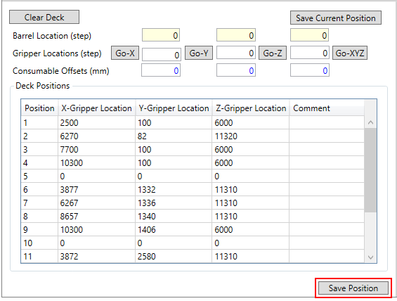
- Arm Coordinates: robotic arm X,Y,Z-coordinates are displayed here that can be saved in the selected deck plate position table record with the “Save Current Location” button. Additional arm controls with “Go-X”, “Go-Y”, “Go-Z”, “Go-XYZ” buttons using single-channel, 4-channel or 8-channel mode selection. Deck plate positions are saved based on the tip barrel location while the tip information is selected here and the plate offsets are loaded when position table rows are selected for X,Y,Z-offset test purposes only.
- Deck Position Table: save X,Y,Z-coordinates in this table or edit them manually. Coordinates refer to the stepper motor steps as the unit of measurement instead of mm. Save table with “Save Position”. Restarting the software might be required if new positions were added.
- Arm Control: individual X,Y,Z-arm control can be conducted here using scrollbars, step value and six directional arrow buttons as well as overall arm initialization and for each axis.
- Arm Test: use “Engage Tips”, “Dispose of Tips”, “Move Arm to Position” to test deck positions and plates with engaged tips. Save with the “Save” button and test additional offsets with “Move Arm to Safety Z-Offset”, “Move Arm to Waste Station”, “Move Arm to Tip Chute”.
- Command Log: robotic arm communication log will be displayed here for troubleshooting purposes.
Robotic arm calibration, configuration, control settings and deck plate positions can be accessed in “Tools → Device Calibration → motor arm”.

Arm Motor Settings tab allows users to customize robotic arm parameters and control settings:
- X,Y,Z Travel Range: maximum robotic arm stepper motor travel limitation in stepper motor steps for each directional axis.
- X,Y,Z Start Speed: initial robotic arm speed in step/s.
- X,Y,Z End Speed: final robotic arm speed in step/s.
- X,Y,Z Acceleration: rate of robotic arm speed change in step/s2.
- X,Y,Z Scale: in mm per robotic arm stepper motor single step for each directional axis.
Click “Save” to update the parameters.

Click “Use Tip” to test deck plate positions with a specific set of tips. Corresponding tip information will be loaded accordingly upon selection.

Deck plate positions are taught and saved in the table for the standard 96-well plate that displays code 21001. The tip barrel #1 is positioned above the A1 well while touching a 4 × 4 cm teaching paper that is placed on top of the plate.

Tip barrels are aligned along the Y-axis and centered along the X-axis as viewed from different angles and confirmed while teaching deck plate positions.

Plate X,Y,Z-offsets can be tested in this window with the “Move Arm to Position” button when position table rows are selected and X,Y,Z-offsets should be manually updated on the Plate Library Offsets right-hand side panel on the top of the main window. All plate offsets are tested when tip barrels touch the teaching paper on top of the plate in the same way as the standard 96-well plate (code 21001).

Tip box X,Y,Z-offsets can be tested in this window with “Move Arm to Position” or “Engage Tips” buttons when position table rows are selected and X,Y,Z-offsets should be manually updated on the Plate Library Offsets panel. Tip box offsets are tested when tip barrels do no engage the tips. In addition to X,Y,Z-offsets, Engagement Depth in Plate Library Offsets should be adjusted manually for such tip barrel tip engagement.

Plate adapter X,Y,Z-offsets can be tested in this window with the “Move Arm to Position” button when position table rows are selected and X,Y,Z-offsets should be manually adjusted in “Plate Library Offsets → Configure Arm Offsets” when the adapter is selected from the list.

Air pump calibration, configuration and control settings are located in “Tools → Device Calibration → air pump”. Both air pump functions such as aspiration and dispensing can be controlled using either stepper motor steps or µL value setting.

Air pump stepper motor steps must not exceed the maximum pump travel range as set in Motorboard Settings in the top-right window panel as well as default air pump speed settings in step/s and step/s2. Click “Save” to update air pump parameters. The priming option isn’t required for the air pump and is only required for the syringe pump which is based on liquid displacement.
The air pump calibration procedure is automated. Select “Air Gap Aspiration”, “Sample Aspiration”, “Time Delay” and press “Perform”. Please use a tube and the weighing boat to aspirate and dispense the liquid sample between defined time delays.
The air pump scale calibration table includes air pump stepper motor steps and the corresponding volume in µL. The maximum air pump volume is defined for the maximum allowed air pump displacement limit. As many individual air pump volumes can be accurately calibrated in the table for specific liquid transfers with such volumes. Please ensure the trendline follows a linear pattern on the graph. Click “Save pump scales” to continue.

Gripper arm calibration, configuration, control settings and gripper positions can be accessed in “Tools → Device Calibration → gripper arm”:
- X,Y,Z Barrel Location: current robotic X,Y-arm and gripper Z-arm coordinates are displayed here and can be saved to the selected gripper position table record with the “Save Current Position”
- X,Y,Z Gripper Locations: gripper table position records are loaded here, additional “Go-X”, “Go-Y”, “Go-Z”, “Go-XYZ” robotic arm / gripper am controls are provided here.
- X,Y,Z Consumable Offsets: deck plate gripper offsets are loaded here either from the Plate Library Offsets or “Plate Library Offsets → Configure Gripper Offsets” in case if an adapter is placed onto the deck.
Click “Save Position” to save the table information.
Robotic X,Y-arm, gripper Z-arm as well as gripper claw control buttons are displayed in this window. Please use corresponding scrollbars or navigational arrow buttons along with the step value setting. The gripper plate transport function between two deck plate positions can be tested with the “Move Plate” button here. An appropriate gripper safety Z-offset can be checked and saved here, as well.

Robotic X,Y-arm speed can be set in Gripper Speed Settings in step/s and step/s2. Gripper Z-arm speed settings for movement to safety Z-offset and during plate engagement are also configured in this window. Click “Save” to continue.

Gripper Z-Axis Motorboard Settings displays the maximum allowed gripper Z-arm travel limit in stepper motor steps, the gripper movement scale in mm/step and the default gripper speed in step/s and step/s2. Press “Save” to continue.

Gripper deck plate positions are saved in the table for the standard 96-well plate that displays code 21001. Gripper claws should be aligned and centered along the X,Y-axis while the Z-axis arm is situated 3 – 5 mm above the deck surface.

Gripper offsets can be tested in this window with the “Move Plate” button after selecting source and target positions when position table rows are selected and the gripper offsets should be adjusted manually on the Plate Library Offsets right-hand side panel on the top of the main window to achieve the correct plate transport functionality using the gripper arm and claw.

Gripper offsets for plates and adapters can be tested in this window with the “Move Plate” button when position table rows are selected and gripper offsets should be manually adjusted in “Plate Library Offsets → Configure Gripper Offsets” when the adapter is selected from the list.

Tip changer configuration and control settings are configured in “Tools → Device Calibration → tip changer”:
- Travel Range: maximum allowed tip changer travel limit in stepper motor steps should be set in such a way that the tips are successfully ejected when using the “Test”
- Cycles: the number of tip changer runs to eject the tips.
- Start Speed, End Speed, Acceleration: applicable tip changer speed settings in step/s and step/s2 for effortless tip disengagement. Click “Save” to continue.
- Engage Tip, Dispose of Tip, Return Tips: tip engagement and disengagement using a tip box are tested here.

Vacuum manifold valve configuration and control settings are configured in “Tools → Device Calibration → vacuum manifold”. Vacuum manifold valves are associated with the deck position where an applicable device such as the nitrogen dryer, the pressure module or the vacuum manifold is mounted. Valve ID is set according to the communication settings. Please use “Open” and “Close” buttons to test the switch valve functionality and observe the result.

Reagent Drop or the PWM pump can be configured, calibrated and controlled in “Tools → Device Calibration → reagent drop”:
- All Pins, Pin 1 – 8: select the required Reagent Drop pin configuration to be used for simultaneous dispensing.
- Dispense, Aspirate: two Reagent Drop or PWM pump functions are available – aspiration and dispensing. For bulk Reagent Drop delivery between several µL and up to several mL, select Dispense.
- Liquid Type, Add Liquid: various liquid classes with different viscosity or viscidity can be selected or added here.
- Cycles: the configuration of PWM valves is used to control the Reagent Drop with the pulse time in µs and the number of distinct cycles, enter the number of cycles here.
- Pulse: during calibration or to bypass the PWM pump calibration, enter the pulse in µs.
- Volume: to validate the PWM pump calibration, use the required Reagent Drop dispensing volume in µL according to the calibration table calculations.

Add various liquid classes with different viscosity or viscidity in this window using the “Add Liquid” button. Different liquid types might also require adjusting the PWM pump pressure in psi in “Tools → Device Calibration → pressure” to ensure accurate reagent delivery.

Reagent Drop pin offsets for the robotic arm positioning on the top-right side of this window are usually configured for the standard 96-well plate (code 21001) but can be tested with any labware that is selected on the instrument deck:
- Pin Group: a software setting used for the Reagent Drop pin reference.
- X,Y,Z-Offset: an offset in mm for each robotic arm axis to align the Reagent Drop pin #1 for the appropriate dispensing into the A1 well of a standard 96-well plate (code 21001) without obstructions.
Click “Update Pin” to continue.

A typical Reagent Drop pin dispensing test with a 96-deep well plate for volumes between 1 – 2 mL.

It is essential to calibrate the Reagent Drop or the PWM Pump to ensure accurate volume delivery on the PWM Scales tab:
- Valve: enter the pin number here that is being calibrated.
- Weight: a scale is required to weigh the dispensed reagent, enter the dispensed volume here in mg.
- Factor: the distilled water will have a viscosity or viscidity factor of 1, adjust its value according to the liquid class.
- Volume: volume in µL is automatically calculated after pressing “Enter” or switching table records.
- Cycles: enter the number of cycles during the Reagent Drop calibration for the selected pin.
- Pulse: enter the pulse in µs during the Reagent Drop calibration for the selected pin.
- Delay: the total dispensing time or delay will be automatically calculated in µs based on the cycles and the pulse time when switching table records or pressing “Enter” on the keyboard.
Press “Update PWM Scales” to save the table.

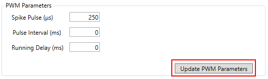
Additional Reagent Drop or PWM Pump settings can be configured on the PWM Parameters tab:
- Spike Pulse: an initial adjustable valve pulse in µs for accurate small volume delivery.
- Pulse Interval: an adjustable delay in ms between pulses or cycles, usually set to zero for continuous dispensing.
- Running Delay: an initial delay in ms before a valve pulse.
Click “Update PWM Parameters” to save the settings.
Reagent Drop or the PWM Pump controls can be adjusted on the right side of this window:
- Move Arm to: the robotic arm needs to be moved towards a selected plate to test the Reagent Drop.
- Position, Column, Row: select the required deck plate position and plate column / row here to test the Reagent Drop.
- Initialize Arm, Lower Tip Changer, Raise Tip Changer: additional instrument controls are provided here for convenience. To test the Reagent Drop, the tip changer bar where it is mounted needs to be lowered.
- Priming, Volume: to ensure accurate Reagent Drop volume delivery, the Reagent Drop tubing needs to be primed. Additionally, the corresponding action in “Tools → Action Configuration → Reagent Drop Priming” can be programmed in assays and sequences so perform such function.

Pressure and vacuum devices can be configured in “Tools → Device Calibration → pressure”:
- Pressure (psi), Vacuum (psi): pressure and vacuum values in psi for the Reagent Drop and vacuum manifold device configuration.
- Set Pressure: sets and retains the pressure and the vacuum at the same time.
- Pressure Adjustment (psi), Vacuum Adjustment (psi): an additional pressure / vacuum calibration adjustment.
- Save Difference Pressure: save and apply pressure / vacuum calibration adjustment.

Temperature control devices, control and configuration settings are available in “Tools → Device Calibration → heater”:
- Position: temperature control deck position selection for a specific channel, two channels can be configured in the software.
- Set Temperature (°C): temperature value setting in °C that is retained once set.
- Tolerance (°C): temperature range in °C within which the temperature is set.
- Adjustment (°C): an additional temperature control calibration adjustment in °C.
- Set Temperature, Check: apply or check the selected temperature settings.
- Update Settings: save the temperature settings.
- Open Monitor, Close Monitor: start the temperature monitor.

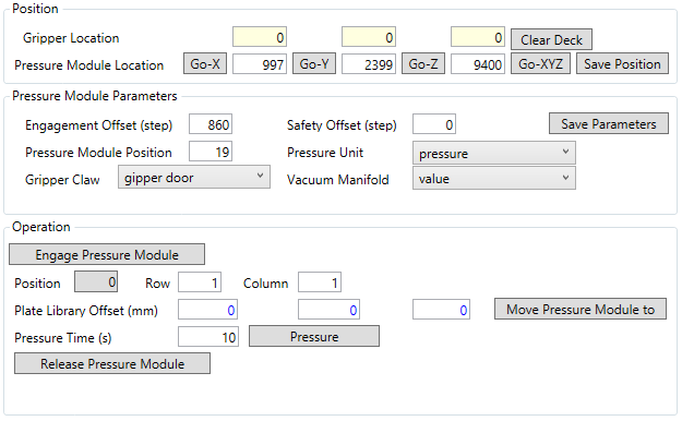
Pressure module device configuration settings and testing options are located in “Tools → Device Calibration → pressure module”:
- X,Y,Z Gripper Location: current robotic X,Y-arm and Z-gripper coordinates.
- X,Y,Z Pressure Module Location: saved coordinates for the pressure module device engagement.
- Go-X, Go-Y, Go-Z, Go-XYZ: test or align each axis for the pressure module device.
- Save Position: save current coordinates for the pressure module device position.
- Engagement Offset: a vertical height in Z-gripper stepper motor steps when gripper speed is reduced and the claw mechanism is open.
- Safety Offset: a vertical height in gripper steps as measured from the top of the gripper axis.
- Pressure Module Position: a designated deck position selection for the pressure module device.
- Gripper Claw: select the gripper device associated with the pressure module.
- Pressure Unit: select the pressure control device associated with the pressure module.
- Vacuum Manifold: select the vacuum manifold device for valve control associated with the pressure module.
- Save Parameters: save the selected pressure module device settings.
- Engage Pressure Module, Release Pressure Module, Move Pressure Module to, Pressure: additional pressure module device and pressure control function buttons.
- Position, Row, Column: select the deck position, plate row and column to move the pressure module device to and apply the pressure.
- Plate Library X,Y,Z Offsets: corresponding plate offsets are loaded here as the reference, pressure module device X,Y,Z-offsets can be adjusted for each plate in “Plate Library Offsets → Pressure X,Y,Z-offsets”.
- Pressure Time: apply the pressure for the specified period of time in sec.
The Pressure Module Speed Settings tab with additional configuration options:
- X,Y Axis: robotic X,Y-arm start speed, end speed in step/s and acceleration in step/s2.
- Engagement: gripper Z-arm speed settings during the pressure module device engagement.
- Movement Up / Down: gripper Z-arm speed settings during the pressure module device vertical movement.
- Update: save the pressure module settings.

The pressure module device gripper engagement position.

Nitrogen dryer device configuration settings and testing options are located in “Tools → Device Calibration → nitrogen dryer”:
- X,Y,Z Gripper Location: current robotic X,Y-arm and Z-gripper coordinates.
- X,Y,Z N2 Dryer Location: saved coordinates for the nitrogen dryer device engagement.
- Go-X, Go-Y, Go-Z, Go-XYZ: test or align each axis for the nitrogen dryer device.
- Save Position: save current coordinates for the nitrogen dryer device position.
- Engagement Offset: a vertical height in Z-gripper stepper motor steps when gripper speed is reduced and the claw mechanism is open.
- Safety Offset: a vertical height in gripper steps as measured from the top of the gripper axis.
- N2 Dryer Position: a designated deck position selection for the nitrogen dryer device.
- Pressure: specified applied nitrogen dryer pressure in psi.
- Gripper Claw: select the gripper device associated with the nitrogen dryer.
- Vacuum Manifold: select the vacuum manifold device for valve control associated with the nitrogen dryer.
- Save Parameters: save the selected nitrogen dryer device settings.
- Engage N2 Dryer, Release N2 Dryer, Move N2 Dryer to, Dryer: additional nitrogen dryer device and pressure control function buttons.
- Position, Row, Column: select the deck position, plate row and column to move the nitrogen dryer device to and apply the pressure.
- Plate Library X,Y,Z Offsets: corresponding plate offsets are loaded here as the reference, nitrogen dryer device X,Y,Z-offsets can be adjusted for each plate in “Plate Library Offsets → Dryer X,Y,Z-offsets”.
- Time: apply the pressure for the specified period of time in sec.

The N2 Dryer Speed Settings tab with additional configuration options:
- X,Y Axis: robotic X,Y-arm start speed, end speed in step/s and acceleration in step/s2.
- Engagement: gripper Z-arm speed settings during the nitrogen dryer device engagement.
- Movement Up / Down: gripper Z-arm speed settings during the nitrogen dryer device vertical movement.
- Update: save the nitrogen dryer settings.

The nitrogen dryer device gripper engagement position.

Shaker devices, control settings and configuration options can be found in “Tools → Device Calibration → shaker”:
- Position: deck device position where the shaker is mounted.
- Address: a communication setting for each shaker device.
- Mixer: indicates if a shaker device a bead mixer.
- Speed: shaking speed in rpm.
- Shaking Time: shaking duration in sec.
- Background: specifies the background shaking mode during liquid handling operations.
- One Direction: check this option for a continuous plate shaking in one direction.
- High-Speed: increased shaking speed mode.
- VP for Motor: motorboard device selection to switch between shaking modes.
- High-Speed Time: shaking duration in sec. for the increased shaking speed mode.
- Shake, Stop: additional shaker device function buttons.
- Start speed: an initial shaker speed adjustment in step/s.
- Acceleration: the rate of speed adjustment in step/s2 for the shaker device.
Click “Update” to save data and continue.

Aspirator device settings and configuration options are displayed in “Tools → Device Calibration → aspirator”:
- Gripper X,Y,Z Location: current robotic X,Y-arm and gripper Z-arm coordinates.
- Aspirator X,Y,Z Location: saved coordinates for the aspirator device engagement.
- Go-X, Go-Y, Go-Z, Go-XYZ: test or align each axis for the aspirator device.
- Save Position: save current coordinates for the aspirator device position.
- Engagement: the aspirator device engagement height in gripper stepper motor steps.
- Safety Offset: a vertical height in gripper steps as measured from the top of the gripper axis.
- Aspirator Position: a designated deck position selection for the aspirator device.
- Gripper Claw: select the gripper device associated with the aspirator.
- Vacuum Manifold: select the vacuum manifold device for valve control associated with the aspirator.
- Save Parameters: save the selected aspirator device settings.
- Position: select the deck position to move the aspirator device to and apply the vacuum.
- Plate Library X,Y,Z Offsets: corresponding plate offsets are loaded here as the reference, aspirator device X,Y,Z-offsets can be adjusted for each plate in “Plate Library Offsets → Aspirator X,Y,Z-offsets”.
- Time: apply the vacuum for the specified period of time in sec.
- Engage Aspirator, Release Aspirator, Move Aspirator to, Remove Waste: additional aspirator device and vacuum control function buttons.

The Aspirator Speed Settings tab with additional configuration options:
- X,Y Axis: robotic X,Y-arm start speed, end speed in step/s and acceleration in step/s2.
- Engagement: gripper Z-arm speed settings during the aspirator device engagement.
- Movement Up / Down: gripper Z-arm speed settings during the nitrogen dryer device vertical movement.
- Update: save the aspirator settings.

The aspirator device gripper engagement position.

On the VERSA 10 workstation only, the plate mover positions and settings are displayed in “Tools → Device Calibration → plate mover”:
- Barrel X,Y,Z Location: current robotic X,Y,Z-arm coordinates.
- Arm X,Y,Z Location: loaded robotic arm position records from the table.
- Go-X, Go-Y, Go-Z, Go-XYZ: test or align each axis for the plate mover device.
- Engagement X,Y,Z Offset: robotic arm offsets in stepper motor steps between the engagement plate mover location and the selected deck plate position.
- Down Offset, Y-Offset, Up Offset: robotic Y,Z-arm offsets in steps for additional plate mover movement.
- Arm: select the robotic arm device associated with the plate mover.
- Update: save the plate mover settings.

The plate mover Speed Settings tab with additional configuration options:
- Down Movement, Y Movement, Up Movement: robotic Y,Z-arm start speed, end speed in step/s and acceleration in step/s2 for additional arm movement.
- Safety Z-Offset: robotic Z-arm speed settings in step/s and step/s2 for plate mover movement to the safety Z-offset.
- Move X,Y,Z-Arm Speed: plate mover speed settings in step/s and step/s2 for each of the robotic arm axes.
- Update: save the plate mover settings.

Plate mover source and target positions can be tested using the “Move” button as well as configuring and saving the safety Z-offset.

The plate mover device engagement position.

The tip chute position and the configuration settings can be accessed in “Tools → Device Calibration → tip chute”:
- Barrel X,Y,Z Location: current robotic X,Y,Z-arm coordinates.
- Arm X,Y,Z Location: robotic arm position coordinates, also saved in “Tools → Device Calibration → motor arm” for positions that are configured as Tip Chute Position in “Tools → Deck Positions”.
- Go-X, Go-Y, Go-Z, Go-XYZ: test or align each axis for the tip chute.
- Save Position: save current coordinates for the tip chute position.
- Drop Tips X,Y,Z Offsets: additional robotic arm offsets in mm for each axis for the tip chute function.
- Moving Direction: the following selection is available – Towards Left, Towards Right, From Front, From Behind.
- Arm: select the robotic arm device associated with the tip chute function.
- Drop Tips Speed: robotic Z-arm speed during the tip disengagement for the tip chute function.
- Update: save the tip chute settings.
- Tip Box Position: deck position selection to test the tip chute function.
- Engage Tip, Dispose of Tip: additional tip changer device controls to test the tip chute function.

Testing and teaching the tip chute position.

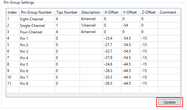
Software settings known as Pin Group are configured in the table in “Tools → Device Calibration → pin group”:
- Pin Group Number: the following selection is available: Pin 1 – 8, Tip 1 – 8, Eight-Channel, Single-Channel, Four-Channel, 96-Channel, Plate Mover.
- Tips Number: the number of tip barrels for the selected pin group setting.
- X,Y,Z Offsets: robotic arm offsets in mm for each axis.
Click “Update” to save the table settings.
If the instrument supports the single-channel liquid level sensing functionality, plate configuration settings can be accessed in “Tools → Device Calibration → lls”:
- Plate or Asymmetrical Plate Matrix: select the plate code that requires LLS calibration settings or an irregular plate partition or matrix which is a symmetric representation of a plate on its own.
- Detection Range: the liquid level sensing capacitance signal increase in reference to the plate or vial / tube surface position; maximum positive value of 255.
- Compensation: robotic arm ± Z-offset in mm to adjust the remaining sample volume calculation based on where the robotic arm should have stopped during the liquid level detection.
- LLS Base Offset: robotic arm positive Z-offset in mm which indicates an additional offset above the very bottom of the plate or vial / tube for the safe arm travel distance.
- LLS Check: these robotic arm speed settings are currently unavailable.
- Arm Aspirating: robotic Z-arm start speed, end speed in step/s and acceleration in step/s2 during the liquid level detection and simultaneous arm movement during air pump aspiration.
- Pump Aspirating: air pump start speed, end speed in step/s and acceleration in step/s2 during the simultaneous robotic arm movement and pump aspiration.
Click “Update” to save these settings for the selected plate type.
For the operation of the liquid level sensing functionality, each plate needs to be calibrate with 8 – 16 records where the maximum depth in mm at the bottom of the plate or vial / tube corresponds to zero volume and zero depth represents the maximum volume in µL at the surface level:
- Depth: robotic arm Z-offset in mm as measured from the plate or vial / tube surface.
- Volume: liquid sample volume in µL within the plate well or vial / tube at the measured depth.
Click “Update Plate LLS Depth” to save the table information for the selected plate type.
The software will automatically calculate the detected sample volume during the liquid level detection based on the linear approximation of the data in the table for each plate type.

Extended error handling and auto-recovery sequences and options have been implemented during the liquid level detection. Liquid level sensing sequences will not be executed without adequate depth / volume pate calibration data. In case of insufficient sample volume detection within the plate well or vial / tube or incorrect liquid level sensing signal detection, various options will be presented to the user:
- OK: re-detect the liquid level in the same plate well or vial / tube.
- Cancel: stop the execution of the entire sequence.
- Skip: skip the insufficient sample volume and locate the next sample in this sequence.

During the liquid level detection, all relevant information is displayed on the status bar including the COM port this liquid level sensing module is using, the capacitance signal, the detected depth and the calculated remaining sample volume. The liquid level sensing signal readings start automatically when the VERSAware Plus software is launched, stop when instrument power is switched off and the COM port is released when the COM port number is updated in “Tools → Electronic Boards, Devices and COM Ports → LLSs Control”.
![]()
![]()
During the liquid level detection sequence, only conductive black pipette tips should be used.

Using the Software
This section will review how to program liquid handling protocols and build sequences with regular actions, single actions and applications as they appear and are customized in “Tools Action → Configuration”. Please create or select an existing sequence, drag and drop the corresponding action to the action configuration panel, program all required parameters and save the sequence with the “Update Current Sequence” toolbar button to create and display the sequence steps. Newly saved sequences can be executed with the “Run current assay or sequence” toolbar button.
Individual actions appear in the action panel on the left side of the main window in the middle.

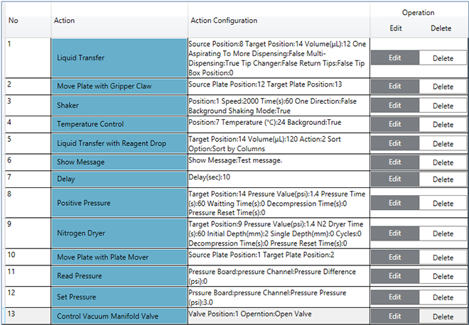
The action table is displayed in the middle of the main window. Drag action records to change the execution order, click “Delete” to remove table action records and “Edit” to modify action parameters. Click “Clear” to erase the entire action table and “Duplicate” to copy the selected action record. Press the “Update Current Sequence” toolbar button to save the sequence, the deck layout, the action table and display the sequence steps that are ready for immediate execution after instrument initialization with the “Initialize all devices and move arm to its original position” toolbar button.
Regular Actions
Regular actions are general liquid handling protocol steps that are commonly used in laboratories for tasks such as pipetting, dilution, mixing and transferring liquids. These protocols are typically programmed using liquid handling automation systems or robotic platforms and they involve a series of actions or steps.
In addition to Liquid Transfer, Liquid Transfer with Reagent Drop can be used to deliver bulk reagents from pressurized bottles by controlling the valves with applied pressure through fixed pins:
- Multi-Channel Transfer: select all Reagent Drop pins for this option.
- Single-Channel Transfer: select any Random Reagent Drop pins in this mode.
- Sort by Columns: will process columns first.
- Sort by Rows: will process rows first.
- Sort by Columns (S-shaped): will process columns first based on the ‘snake pattern’.
- Sort by Rows (S-shaped): will process rows first based on the ‘snake pattern’.
- Aspirate: an option reserved for the Reagent Drop operations with vacuum.
- Dispense: select this option for the Reagent Drop volume delivery based on pressure.
- Liquid Type: select the liquid class that is calibrated in “Tools → Device Calibration → reagent drop”.
- Volume: Reagent Drop delivery volume in µL.
Click “Save” to update the settings and close the window.

The plate transport function can be conducted using Move Plate with Gripper Claw:
- Gripper Claw: select the appropriate gripper claw device for this function.
- Source Position: plate deck selection interface for the source position.
- Target Position: plate deck selection interface for the destination position.
Click “Save” to save the parameters and continue.

The temperature control function can be performed with Temperature Control:
- Temperature Position: deck position selection interface, the position also needs to be configured in “Tools → Device Calibration → heater”.
- Temperature: the temperature setting value in °C.
- Background Temperature Control: indicates if temperature control is conducted during the liquid handling operations.
Click “Save” to save the options and close the window.

The instrument shaking capability is provided by Shaker:
- Position: deck position selection interface, the position will also need to be selected in the table in “Tools → Device Calibration → shaker”.
- Speed: the shaking speed in rpm.
- Shaking Time: shaking duration in hr, min and sec.
- One Direction: select the continuous shaking mode in a single direction or alternating in both directions.
- Background Shaking Control: indicates if shaking is performed during other liquid handling operations.
Click “Save” to update the settings and continue.

A custom message display during sequence execution is available with Show Message. Click “Save” to save the message and continue.

Liquid Transfer with Different Channels is similar to Liquid Handling with the exception of specific channel-mode option selection. Enter volume in µL, select various transfer modes such as “Multi-Dispensing”, other tip box options, choose deck plate positions, color selection, corresponding source and target wells, and click “Save” to continue. Optional mixing settings are available, as well. Pay attention to correctly match source and target well colors for the valid sequence to be created and saved.

A random time delay sequence step can be added to a sequence with time delay setting value in hr, min and sec. Click “Save” to update the settings and continue.

The VERSA 10 instrument will also feature Move Plate with Plate Mover. Select the appropriate plate mover device, source and target deck positions, click “Save” to save the options and close the window.

Optional Reagent Drop priming can be performed with Reagent Drop Priming to improve volume delivery accuracy in sequences:
- Source: Reagent Drop pin selection interface.
- Reagent Drop: Reagent Drop device selection.
- Liquid Type: liquid class selection as configured in “Tools → Device Calibration → reagent drop”.
- Volume: Reagent Drop volume setting value in µL.
Click “Save” to update the settings and continue.

The N2 dryer application can be programmed in sequences using Nitrogen Dryer:
- N2 Dryer Target Position: select the deck plate position where the nitrogen dryer will be applied.
- Pressure Value: nitrogen dryer device pressure setting value in psi.
- N2 Dryer Time: duration of the nitrogen dryer application in sec.
- Initial Depth: initial depth in mm where the nitrogen dryer is applied.
- Single Depth: additional depth in mm for the nitrogen dryer application.
- Cycles: the number of times the nitrogen dryer is applied.
Click “Save” to save this information and close the window.

The pressure module can be programmed in sequences using Positive Pressure:
- Pressure Target Position: select the deck plate position where the pressure module will be applied.
- Pressure Module Rows: the number of channels for the pressure module device.
- Pressure Value: the positive pressure setting value in psi.
- Pressure Time: duration of the positive pressure application in sec for each plate column.
- Waiting Time: time delay in sec after positive pressure application for each plate column.
- Decompression Time: duration of the positive pressure application in sec before pressure module engagement.
- Pressure Reset Time: time delay in sec before pressure module engagement.
Click “Save” to update the parameters and continue.

Waste Removal with Tips can also be programmed using Liquid Transfer for the waste position that is configured in “Tools → Deck Positions”:
- Source Position: select the deck plate position.
- Target Position: select the waste station deck position.
- Multi-Channel Transfer: 4-channel or 8-channel transfer mode selection.
- Single-Channel Transfer: single-channel transfer mode selection.
- Volume: sequence transfer volume in µL.
- Tip Changer: tip disposal for each source plate column or liquid transfer.
- Return Tips Back to Tip Box: returning the tips to the original tip box after each liquid transfer.
- Tip Box Position: tip box selection for the designated sequence, an automatic tip box assignment will be made by the software if no tip box is selected.
Click “Save” to save the configuration settings and close the window.

Alternatively, Waste Removal with Aspirator can be used to dispose of the waste liquid from plates using vacuum if the instrument is equipped with such aspirator:
- Waste Liquid Disposal / Target Position: select the deck plate position.
- Aspirator: aspirator device selection.
- Disposal Time: duration of aspirator vacuum application in sec.
- Disposal Depth: the height in mm for aspirator movement above the plate.
Click “Save” to update the options and continue.

Mixing with Tips can be programmed as a stand-alone action as well as being part of Liquid Transfer and other liquid handling actions:
- Mixing Cycles: the number of runs during plate mixing.
- Liquid Aspiration Volume: the mixing volume in µL.
- Liquid Aspiration Depth: the aspiration height within the plate.
- Liquid Dispensing Depth: the dispensing height within the plate.
- Air Dispensing Depth: the dispensing height for the air gap within the plate.
Click “Save” to save the settings and close the window.

Set Sample, Add Reagent to Sample, Aspirate Waste for Sample and Sample Collection all work together in a bundle and the parameters are adjusted by the software according to the Set Sample settings as programmed by users.

Set Sample is used in conjunction with Add Reagent to Sample, Aspirate Waste for Sample and Sample Collection:
- Multi-Channel Transfer: 4-channel or 8-channel transfer mode selection.
- Single-Channel Transfer: single-channel transfer mode selection.
- Magnetizing Position: this deck position is used as the source position in Aspirate Waste for Sample and Sample Collection.
- Reagent Tip Box Position: a tip box used in Add Reagent to Sample.
- Tip Box Position for Collection and Waste Handle: a tip box used in Aspirate Waste for Sample and Sample Collection.
Click “Save” to update the options and continue.

Set Sample should precede Add Reagent to Sample:
- Volume: transfer volume value setting in µL.
- Reagent Dispensing Depth: reagent dispensing height in mm, this setting overwrites “Sequence Settings → Plate Parameters → Dispensing Z-Offset”.
- Reagent Addition Mode: the following selection is available – All Samples, Each Column.
- Tip Changer: tip disposal for each source plate column or liquid transfer.
- Return Tips Back to Tip Box: returning the tips to the original tip box after each liquid transfer.
- Same Tips for Mixing After Liquid Transfer: the same pipetting tips will be used during mixing.
- Tip Box Position: tip box selection for the designated sequence, the tip box position will be assigned by Set Sample if no tip box is selected.
Click “Save” to save the settings and close the window.
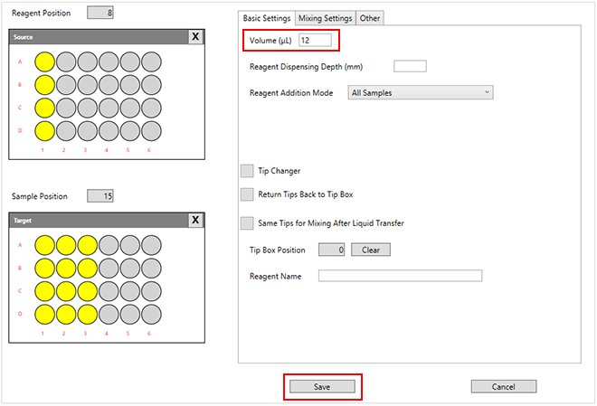
Set Sample should precede Aspirate Waste for Sample. Source position is configured by Set Sample, target position is set according to Waste Position in “Tools → Deck Positions”:
- Volume: transfer volume value setting in µL.
- Tip Changer: tip disposal for each source plate column or liquid transfer.
- Return Tips Back to Tip Box: returning the tips to the original tip box after each liquid transfer.
- Tip Box Position: tip box selection for the designated sequence, the tip box position will be assigned by Set Sample if no tip box is selected.
Click “Save” to save the data and continue.

Set Sample should precede Sample Collection. Source and target positions are configured by Set Sample:
- Volume: transfer volume value setting in µL.
- Tip Changer: tip disposal for each source plate column or liquid transfer.
- Return Tips Back to Tip Box: returning the tips to the original tip box after each liquid transfer.
- Tip Box Position: tip box selection for the designated sequence, the tip box position will be assigned by Set Sample if no tip box is selected.
Click “Save” to update the options and close the window.

Liquid Pump Priming should only be used with syringe pumps if the instrument is equipped with such devices:
- Pump: select the relevant syringe pump device.
- Pump Channel: the following selection is available: All Channel, 1 Channel – 8 Channel.
- Cycles: the number of runs during the syringe pump priming.
- Back Aspiration Volume: air gap volume in µL which is aspirated to separate the system fluid.
Click “Save” to update the parameters and continue.

Single Actions
Calibrating liquid handling workstations is a critical step to ensure the accuracy and precision of liquid transfers. Calibration typically involves a series of single actions or operations that are performed to set the equipment to a known reference standard. These actions can include: volume calibration, Z-axis calibration, tip calibration, accuracy verification, precision verification, calibration of additional features, software calibration, environmental factors and validation.
Robotic arm movement for an individual axis can be programmed with Move Arm. Select the appropriate robotic arm device, axis and enter the stepper motor step. Click “Save” to save the settings.

Control Vacuum Manifold Valve can be used to validate the switch valve control functionality. Select the appropriate deck device position and the operation mode. Click “Save” to continue.
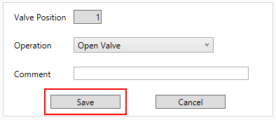
Control Motor Board Valve is used to test the syringe pump functions and other devices. Select the appropriate device, the motorboard address and the operation mode. Click “Save” to close the window.

Initialize All Devices (no parameters) and Initialize Motor Board can be scheduled for all devices compatible with motorboard control functions. Select the corresponding device and the motorboard axis. Click “Save” to update the settings.

Read Pressure is an individual action that can be used for pressure calibration for devices such as the Reagent Drop or for vacuum calibration for devices like the aspirator. Select the associated pressure board, the operation mode and the adjustment setting value in psi. Click “Save” to save the configuration.

Set Pressure is an individual action that can be used for pressure calibration for devices such as the Reagent Drop or for vacuum calibration for devices like the aspirator. Select the associated pressure board, the operation mode and the pressure / vacuum setting value in psi. Click “Save” to continue.

Control Tip Changer is available for the tip changer operation. Select the appropriate tip changer device and the operation mode. Click “Save” to save the parameters.

Stop Shaker is used to interrupt the shaking process. Select the suitable shaker device deck position according to “Tools → Device Calibration → shaker”. Click “Save” to save the options.
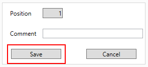
Gripper Open or Close should be used to control the gripper claw device. Select the relevant gripper claw device and the operation mode. Click “Save” to close the window.

Applications
Liquid handling applications involve the precise and automated manipulation of liquids in a laboratory or industrial setting. These applications are crucial in various fields, such as biology, chemistry, pharmaceuticals and diagnostics. Implementing protocols in liquid handling applications ensures accuracy, consistency and repeatability in experiments and processes.
Serial Dilution is used to program an application to be carried out by the liquid handling instrument:
- Source Position: the source deck plate position selection interface.
- Target Position: the destination deck plate position selection interface.
- Diluent Position: the diluent deck reservoir position selection interface.
- Concentration: source plate sample concentration in mM or µM.
- Max Concentration: required maximum first-column sample concentration in µL in the target plate.
- Volume: the total volume in µL in the target plate at the time of the serial dilution.
- Final Volume: calculated by the software, the diluent distribution volume in µL according to the log scale setting that also comes to be the total volume in the target plate after the serial dilution.
- Dilution Multiples (Log Scale): enter the log scale value setting, so the target plate concentration can be calculated as T = C L– i where T is the target plate concentration, C is the maximum target plate concentration, L is the log scale setting and i is the target plate column or sample well.
- Last Column Liquid Handling Volume: last-column volume adjustment in µL in the target plate.
- Multi-Channel Transfer: 4-channel or 8-channel transfer mode selection.
- Single-Channel Transfer: single-channel transfer mode selection.
- Diluent Single Aspiration and Multi-Dispensing: indicate if multi-dispensing is used for the diluent distribution.
- Tip Changer for Sample Transfer: dispose of the tips for each target plate column or sample.
- Tip Changer when Uniform Volume: dispose of the tips for the last target plate column or sample.
- Return Tips Back to Tip Box: returning the tips to the original tip box after each liquid transfer.
- Mix with the Same Tips After Liquid Transfer: engage new tips if sample mixing is required.
- Tip Box Position: tip box selection for the designated sequence, the tip box position will be assigned by the software if no tip box is selected.
- Residual Diluent Volume Mode: the following selection is available – At Source Position, At Waste Position.
Click “Save” to update the options and close the window.

Read-only target plate sample concentration table in µM according to the log scale setting in Serial Dilution.

Normalization is available to program an application to be conducted by the liquid handling workstation:
- Source Position: the source deck plate position selection interface.
- Target Position: the destination deck plate position selection interface.
- Diluent Position: the diluent deck reservoir position selection interface.
- Normalize to: the required target plate concentration in µg/mL.
- Final Volume: the total volume in µL in the target plate after the normalization.
- Multi-Channel Transfer: 4-channel or 8-channel transfer mode selection.
- Single-Channel Transfer: single-channel transfer mode selection.
- Diluent Single Aspiration and Multi-Dispensing: indicate if multi-dispensing is used for the diluent distribution.
- Tip Changer for Sample Transfer: dispose of the tips for each target plate column or sample.
- Return Tips Back to Tip Box: returning the tips to the original tip box after each liquid transfer.
- Mix with the Same Tips After Liquid Transfer: engage new tips if sample mixing is required.
- Tip Box Position: tip box selection for the designated sequence, the tip box position will be assigned by the software if no tip box is selected.
- Residual Diluent Volume Mode: the following selection is available – At Source Position, At Waste Position.
Click “Save” to update the options and close the window.

Normalization is available to program an application to be conducted by the liquid handling workstation:
- Source Row: source plate sample well row, works according to the well selection interface.
- Source Column: source plate sample well column, works according to the well selection interface.
- Sample Name: sample name can be entered by users or imported.
- Sample ID: sample ID can be entered by users or imported.
- Original Concentration: source plate sample concentration is entered by users or imported.
- Original Sample Volume: source plate sample volume is entered by users or imported.
- Target Row: target plate well row, works according to the well selection interface.
- Target Column: target plate well column, works according to the well selection interface.
- Required Concentration: entered by users on the main interface as Normalize to (µg/mL).
- Diluent Volume: calculated by the software in µL.
- Sample Volume: calculated by the software in µL.
- Final Volume: entered by users on the main interface as Final Volume (µL).
Click “Save” to save the settings and continue.

Click “Import” or “Export” to work with an appropriate MS Excel file or spreadsheet to automate the normalization application task.
